Tips for proper installation
![]() All headless screws in corner connections, cross connections and passageway connections as well as transformers must be tightened firmly. All cable connections with external feed should be checked for tightness. The knurled-head screws of the spotlights must firmly be tightened, even if the lamp already has contact. All illuminants should be checked for a solid seat when inserting. The current relay must be activated by pressing the memory key for taking over the nominal load.
All headless screws in corner connections, cross connections and passageway connections as well as transformers must be tightened firmly. All cable connections with external feed should be checked for tightness. The knurled-head screws of the spotlights must firmly be tightened, even if the lamp already has contact. All illuminants should be checked for a solid seat when inserting. The current relay must be activated by pressing the memory key for taking over the nominal load.
![]() The distance of the conductor rail from the ceiling or the wall amounts to min. 6cm. To avoid bending the rail by own and spotlight weight, the distances between the fastenings should amount to on the ceiling max. 0.70m and on the wall max. 0.50m.
The distance of the conductor rail from the ceiling or the wall amounts to min. 6cm. To avoid bending the rail by own and spotlight weight, the distances between the fastenings should amount to on the ceiling max. 0.70m and on the wall max. 0.50m.
For safety reasons no objects may be attached to the conductor rail to the decoration or the like.
Current relays or overcurrent protection switches and transformers should be mounted easily accessible. The transformer used externally should be installed at the rail feeding as near as possible.
Information on transformers
![]() The given transformer capacity determines the number and the capacity of the illuminants.
The given transformer capacity determines the number and the capacity of the illuminants.
Example:
12V / 105VA transformer = 3 x 12V / 35W bulbs
![]() Pay attention to the minimum load of the transformer:
Pay attention to the minimum load of the transformer:
transformer capacity 105VA :: minimum load 60W
transformer capacity 210VA :: minimum load 120W
transformer capacity 300VA :: minimum load 220W
Please note that with the utilization of the transformer the resistance of the busbar and connections are taken into account.
For safety reasons only Sölken transformers which are equipped with a protective device have to be installed.
Ceiling fasteners with further wiring
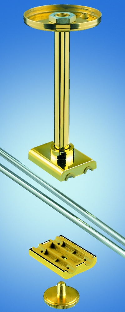 Distance of the low volt bus conductors from the ceiling
The distance to the ceiling is eligible between 6cm or 22cm.
![]()
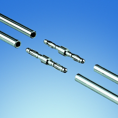 Further wiring
The plug connector 9204 can be used in any arbitrary place of the system for the further wiring.
![]()
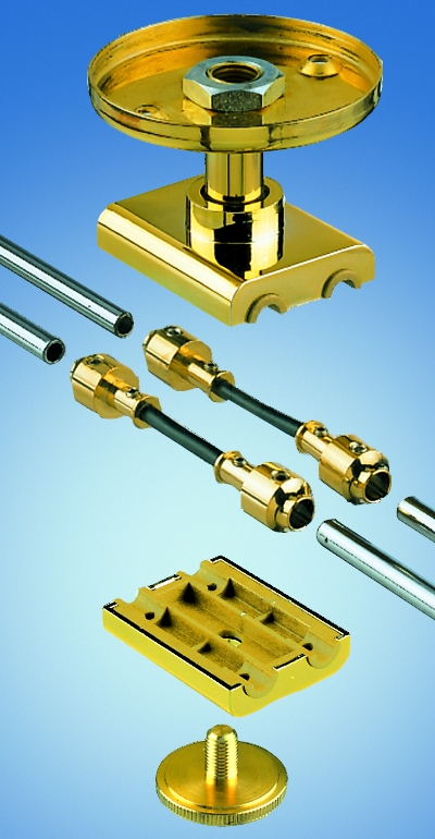 Spacing of fasteners
The distances between the fasteners (here ceiling fastener 9113 with gateway conductor 9205) should amount to max. 0.70m on the ceiling.
With horizontal arrangement of the bus conductor rails on the wall the distances between the fasteners should be not greater than 0.50m.
![]()
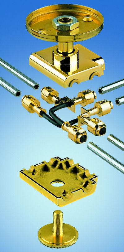 T connector
The ceiling fastener 9115 is used completely as a T joint with further wiring.
A feeding is not possible.
![]()
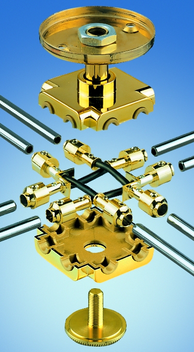 Cross connector
The ceiling fastener 9117 is used completely as a cross continuity fitting with further wiring.
A feeding is not possible.
![]()
Feeding variations
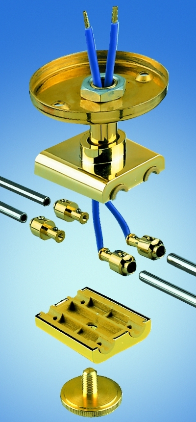 New feeding and separation with distance bolt 9206
Here the gateway conductor 9205 must get separated. Then screw together the secondary connection (12V) in the separated gateway conductor.
Max. cross-section 2,5mm2.
![]()
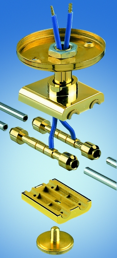 Feeding for mutual current conduction
Here the feeding 9208 is used.
Max. cross-section 4mm2.
![]()
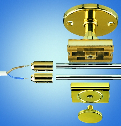 External feeding (12V)
Here the feeding 9202 is used.
Cross-section 6mm2.
![]()
Curves
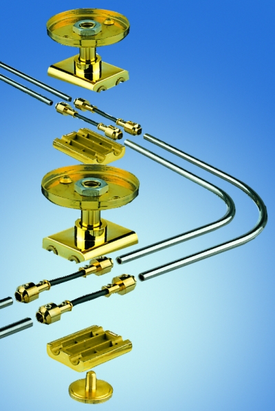 Curve connection
With the corner, floor or flexible connector the gateway conductor 9205 must be put together into the ceiling fastener in principle.
![]()
Termination
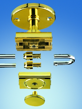 Termination of the bus bar conductor system
As a final assembly help or to the avoidance of short circuits insert distance bolt 9206.
The endpiece 9302 may get no connection with the bus conductor.
![]()
Spotlights
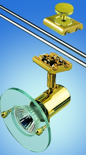 Spotlights
The spotlights have to be fastened to the rail at any arbitrary position.
Retail Shop
Lichtservice Schrader
Distributor
Owner: Stefan Schrader
Lamp Expert
Luruper Hauptstr. 125
22547 Hamburg
Tel.: 040 - 831 99 64
Fax: 040 - 832 10 353
E-Mail:
office@lichtservice-schrader.de
Open
Mo - Fr 9 a.m. - 6 p.m.
Sa 10 a.m. - 1 p.m.
Photos
![]() The photos can be enlarged with a click on the thumbnail, what will be the case as a rule provided that the JavaScript option of your browser is activated. The separate window opening then can be closed again with a click on the blowup.
The photos can be enlarged with a click on the thumbnail, what will be the case as a rule provided that the JavaScript option of your browser is activated. The separate window opening then can be closed again with a click on the blowup.

